
Choosing the best Solid State Frequency Converters in 2026 requires more than comparing brand names or advertised efficiency. A converter may look impressive on paper, yet perform poorly in a hot control room, beside a sensitive motor, or under unstable grid conditions. This guide examines practical performance, including frequency accuracy, harmonic distortion, thermal behavior, overload capacity, switching response, service support, and expected operating life.
Dr. Frede Blaabjerg, a leading power electronics researcher, has stated, “Power electronics is the key enabling technology for renewable energy systems.” His observation also applies to modern frequency conversion, where compact semiconductor systems control motors, generators, aircraft equipment, industrial drives, and renewable-energy assets. The strongest Solid State Frequency Converters should therefore be judged as complete systems, not isolated circuit boards.
Real-world experience matters.
A reliable unit should maintain stable output during rapid load changes. Its enclosure should protect sensitive components from dust, vibration, and heat. Engineers should also review cooling design, electromagnetic compatibility, maintenance access, and documented compliance testing. Manufacturer claims deserve careful verification through datasheets, independent test reports, and installation references.
Still, no universal winner exists. A converter optimized for laboratory precision may not suit a steel plant or remote wind site. This comparison will identify leading technologies and manufacturers, while acknowledging an uncomfortable limitation: field-failure data is often incomplete or difficult to compare. That gap deserves attention. The final choice should match the application, not merely the highest efficiency figure.
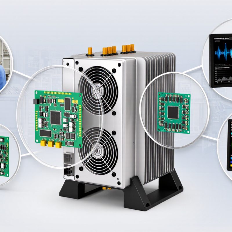
Which Solid State Frequency Converters Are Best in 2026?
Solid-state frequency converters use semiconductor switching to change electrical frequency without mechanical moving parts. IEC 60146 provides a useful technical framework for describing their topology, operating conditions, and ratings. A common configuration is the indirect converter: an AC input feeds a rectifier, a DC link, and an inverter. This arrangement supports controlled output frequency and voltage. Direct converters, including cycloconverter and matrix-converter designs, reduce or remove the DC-link stage. Their behavior differs under low-speed operation, regeneration, and harmonic loading.
Ratings must be read as operating limits, not marketing labels. Check rated input voltage, output current, frequency range, overload duration, cooling method, and permissible ambient temperature. A converter rated at 400 V and 100 A may not deliver that current continuously at 50°C. IEC 60146-based specifications also help identify commutation requirements, semiconductor protection, insulation levels, and test conditions. These details matter in a cabinet with restricted airflow or frequent acceleration cycles. Keep the margin realistic. Oversizing can increase cost, while undersizing may trigger thermal trips.
Topology alone does not define the best choice. A voltage-source inverter may suit a pump, while a regenerative process needs a different front end. Harmonic performance, fault response, motor compatibility, and maintenance access should be checked together. The comparison is rarely tidy. A clean rating table can still hide derating assumptions. Expect to question unclear test conditions.
| Topology | IEC 60146-Related Classification | Power Conversion Path | Typical Output Frequency | Typical Power Range | Main Strengths | Main Limitations | Best-Fit Applications in 2026 |
|---|---|---|---|---|---|---|---|
| Voltage-Source Inverter (VSI) Drive | Self-commutated semiconductor converter; normally an AC–DC–AC indirect converter | AC input → diode, thyristor, or active rectifier → DC link capacitor → PWM inverter → AC output | 0 Hz to the motor-rated frequency; commonly 0–400 Hz, with higher values in special-duty systems | Approximately 0.25 kW to several MW, depending on voltage class and cooling design | High efficiency; wide speed range; precise torque control; regenerative operation possible with an active front end | DC-link capacitor aging; switching electromagnetic interference; input harmonics when a passive rectifier is used | General-purpose motors, pumps, fans, compressors, conveyors, machine tools, HVAC, and energy-efficient industrial drives |
| Active Front-End VSI | Self-commutated converter with controlled input-side semiconductor switching | AC input ↔ PWM active rectifier ↔ DC link ↔ PWM inverter ↔ AC output | Typically 0 Hz to 400 Hz or more, subject to motor and switching design | Approximately 10 kW to multi-MW systems | Near-unity or controllable power factor; low input current distortion; four-quadrant power flow; regenerative braking | Higher control, filtering, and semiconductor complexity; switching losses can exceed those of a diode front end | Cranes, elevators, test stands, centrifuges, rolling equipment, regenerative hoists, and installations with strict power-quality limits |
| Current-Source Inverter (CSI) Drive | Self-commutated or load-commutated converter using a substantially controlled DC-link current | AC input → controlled rectifier or active converter → DC-link reactor → current-source inverter → AC output | Typically from near zero to the motor-rated frequency; application-specific high-speed operation is possible | Commonly used from several hundred kW to multi-MW ratings | Regenerative capability; robust short-circuit behavior; long motor-cable suitability; reduced dependence on large DC-link capacitors | Lower low-speed torque capability in some designs; motor compatibility and commutation requirements must be checked carefully | Large compressors, pumps, fans, mills, marine drives, and high-power applications where regenerative operation is valuable |
| Load-Commutated Inverter (LCI) | Line- or load-commutated thyristor converter; a specialized current-source drive arrangement | AC → controlled thyristor rectifier → DC smoothing reactor → thyristor inverter → synchronous motor | Usually limited to low fundamental output frequency during starting and normal motor-speed operation | Generally approximately 2 MW to more than 50 MW in industrial installations | Efficient at very high power; mature thyristor technology; suitable for large synchronous motors | Requires a suitable synchronous motor; input and output harmonics; motor power factor and commutation limits require detailed studies | Large compressors, pumps, fans, mine hoists, rolling mills, and high-power process equipment |
| Cycloconverter | Direct AC-to-AC line-commutated semiconductor frequency converter | AC input → phase-controlled bidirectional thyristor bridges → variable-frequency AC output; no intermediate DC link | Normally below approximately one-third of the input frequency for practical waveform quality | Typically several MW to tens of MW | Very high power capability; direct power conversion; excellent low-speed torque for large synchronous motors | Large input harmonic content; poor displacement factor at low output frequency; bulky phase-shifting arrangements may be required | Ball mills, cement mills, mine hoists, ship propulsion, and very large low-speed motor drives |
| Matrix Converter | Direct self-commutated AC-to-AC converter using bidirectional semiconductor switches | AC input → bidirectional switch matrix → variable-voltage, variable-frequency AC output; no DC-link energy-storage capacitor | From near zero to a practical maximum commonly below the input frequency; control-dependent | Commonly applied from a few kW to several hundred kW; higher ratings are possible but less common | Compact energy storage; bidirectional power flow; controllable input power factor; high dynamic response | More complex commutation and protection; voltage transfer ratio is limited; sensitive to input disturbances | Compact industrial drives, aerospace test equipment, machine tools, and applications requiring bidirectional AC power conversion |
| Modular Multilevel Converter (MMC) | Self-commutated multilevel voltage-source converter composed of series-connected submodules | AC ↔ modular submodule arms with distributed capacitors ↔ AC output or medium-/high-voltage conversion stage | Grid-frequency and variable-frequency operation; output frequency depends on the control and application | Typically hundreds of kW to hundreds of MW | Scalable voltage capability; low output distortion; reduced filter requirements; redundant submodule options | Large control-system and protection burden; capacitor-voltage balancing and submodule reliability are critical | Medium-voltage drives, grid interfaces, STATCOM systems, large motor drives, and high-power energy conversion |
| Rating Dimension | What It Defines | Typical Engineering Selection Consideration |
|---|---|---|
| Rated input voltage and frequency | The intended AC supply voltage, number of phases, and frequency range | Select the converter for the actual system voltage, short-circuit level, frequency tolerance, and insulation coordination requirements |
| Rated direct current or output current | The continuous current capability under specified cooling and ambient conditions | Check motor full-load current, overload duty, altitude derating, enclosure cooling, and semiconductor thermal limits |
| Rated apparent power | The converter power capability expressed in VA, kVA, or MVA | Compare both kW and kVA because input power factor, harmonics, and reactive power affect equipment sizing |
| Overload and short-time duty | Permitted current and duration above the continuous rating | Match the overload profile to acceleration torque, crusher or mill starting, hoisting cycles, and regenerative braking events |
| Commutation method | Whether switching depends on the AC supply, the load, or actively controlled semiconductor devices | Self-commutated topologies generally provide broader control; line- and load-commutated designs can be advantageous at very high power |
| Harmonic performance | Input and output current or voltage distortion produced by the converter | Evaluate the complete installation, including line reactors, passive or active filters, motor cables, and grid-code requirements |
| Cooling and service conditions | Thermal environment, cooling medium, installation altitude, enclosure, and duty cycle | Apply the manufacturer’s derating curves and verify semiconductor junction temperature, airflow, redundancy, and maintainability |
Note: IEC 60146 establishes general requirements and rating principles for semiconductor converters; it does not designate one universal “best” topology. The ranges above are typical engineering envelopes, not mandatory IEC limits, and must be verified against the converter’s declared operating conditions and project specifications.
No. It may reflect one ideal operating point. Request results at 25%, 50%, 75%, and 100% load.
Compare watts per cubic inch, airflow, acoustic output, and service clearance.
Higher switching frequency can reduce magnetic component size.
Evaluate harmonics at the point of common coupling, not only at converter terminals.
Ask for voltage conditions, load ranges, system strength, and short-circuit ratio.
Request independent reports covering immunity and emissions under stated test conditions.
Not completely. MTBF may be calculated rather than proven in field operation.
Compare fan replacement intervals, airflow direction, filter access, standby consumption, and derating curves.
Include purchase price, energy use, planned parts, downtime exposure, and disposal requirements.
Solid State Frequency Converters are evaluated in 2026 by combining IEC 60146 topology definitions with practical ratings for voltage, power, frequency, and operating environment. The best designs typically deliver 98–99% efficiency while balancing power density, thermal performance, and compliance with IEEE 519 harmonic limits. PWM converters offer flexible control and broad industrial applicability, matrix converters provide compact bidirectional operation, and cycloconverters remain valuable for very high-power, low-frequency systems. Each topology must be matched carefully to the requirements of grid infrastructure, aviation, marine equipment, or industrial machinery.
A reliable selection should also consider IEC 61000 electromagnetic compatibility, expected MTBF, cooling architecture, serviceability, and total lifecycle cost rather than purchase price alone. In 2026, the strongest Solid State Frequency Converters will combine efficient semiconductor switching, stable output quality, robust protection, scalable installation, and predictable maintenance needs. Comparing these factors across operating conditions helps users choose a converter that delivers long-term performance, regulatory compatibility, and dependable energy conversion.