
Choosing the right Modular DC Electronic Loads starts with the job they must perform. A bench setup for validating a 48-volt power supply has different needs from a production rack testing several outputs at once. Consider voltage and current ranges, power dissipation, channel count, and how long each test will run. Check the load’s operating limits against the device under test, not just its headline rating. A unit rated for high power may still need reduced capacity at certain voltages or ambient temperatures. Read the specifications carefully.
Modularity can make a test system easier to expand, but it does not guarantee a good fit. Review how modules share control, cooling, and measurement resources. Confirm that the chassis can handle the combined heat, especially during sustained constant-current tests. Then look at practical details: front-panel access, remote interfaces, data logging, and the clarity of protection alarms. Small details matter.
A useful selection process also considers future maintenance. Can a failed module be replaced without disrupting every test? Are calibration requirements and support options clearly documented? These questions can feel less urgent during procurement. They matter later. Compare candidate systems using the same test conditions, and verify key readings with suitable measurement equipment. No checklist replaces a careful evaluation of the actual test setup. Some requirements will change once engineers begin using the system, so leave room for that reality.
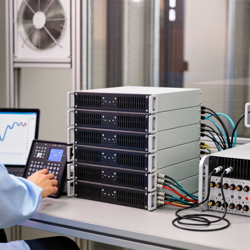
Before choosing a modular DC electronic load, define exactly what the test must prove. Record the source’s maximum voltage, current, and power, including brief peaks rather than only nominal ratings. A supply rated at 48 volts may overshoot during startup. The load must tolerate that condition without exceeding its input limits. Leave operating headroom; using every rating at once can create avoidable thermal stress.
Specify the load profile: steady-state draw, pulsed current, ramp rate, and transient duration. For example, a battery converter test may require a 10-amp draw followed by a fast step to 25 amps. Check whether the planned modules can handle both the step and repeated operation. Small details matter. Define connection type, number of test channels, and whether measurements must be synchronized. Also note ambient temperature, airflow, and available rack space, since tightly packed equipment may derate sooner than expected. One requirement is easy to overlook: how results will be recorded and compared. Set measurement accuracy and logging intervals before testing begins. If the profile is still uncertain, document that uncertainty and leave room to revise it; guessing can make a technically capable load unsuitable.
Modular DC electronic loads combine plug-in load channels inside a shared chassis. A controller coordinates modules, while each channel draws current from the device under test. Parallel operation can increase available current or power, but only within the system’s voltage limits and current-sharing capability. Check whether channels operate independently, share a common bus, or require matched modules. Small differences matter.
Choose specifications around the test, not the headline power rating. Confirm voltage and current ranges, constant-current, constant-voltage, constant-resistance, and constant-power modes, plus transient response and slew rate. For battery and power-converter work, also check measurement accuracy, protection limits, cooling, and whether energy is dissipated as heat or returned to the grid. The IEA’s Global EV Outlook 2024 reports nearly 14 million electric-car sales in 2023, about 18% of global car sales. That growth makes repeatable battery testing more important, but a large load rating alone does not ensure realistic test conditions.
Tips: Leave headroom above expected peak power. Verify module sharing with a real load, and watch for temperature rise during long tests. Datasheets can look reassuring; the wiring may tell a different story.
| Selection Dimension | What to Check | How to Interpret It | Practical Guidance |
|---|---|---|---|
| System architecture | Chassis, plug-in load modules, power connections, cooling, and control interface. | A modular load combines one or more load modules in a shared enclosure or system. The chassis may provide power distribution, communications, cooling, or synchronization. | Confirm which functions are built into the chassis and which require separate modules or accessories. |
| Channel configuration | Number of independent channels and whether modules can operate independently. | A channel typically has its own input terminals and control settings. Multiple modules do not necessarily equal multiple independent channels. | Match channel count to the number of devices under test (DUTs) that must be tested at the same time. |
| Module combination | Supported parallel operation, current sharing, master-slave control, and module compatibility. | Parallel operation can increase available current or power only when the system is designed to coordinate the modules. Series operation is not universally supported. | Check the operating manual for approved combinations, wiring, and derating requirements. |
| Voltage range | Minimum operating voltage, maximum input voltage, and any voltage-dependent limits. | The DUT voltage must remain within the load's specified input range. Maximum voltage, current, and power limits may not be available simultaneously. | Allow margin above the DUT's highest expected voltage, including transients where applicable. |
| Current and power ratings | Continuous current, continuous power, peak limits, and derating curves. | For a DC load, input power is approximately voltage multiplied by current: P = V × I. The operating point must stay within all applicable ratings. | Size the load for the required test point and duty cycle, not just the DUT's nominal rating. |
| Operating modes | Constant current (CC), constant voltage (CV), constant resistance (CR), and constant power (CP), if available. | Each mode regulates a different electrical quantity. Mode availability and performance can depend on voltage, current, and power limits. | Choose modes that correspond to the DUT behavior or test procedure being simulated. |
| Dynamic response | Programmable slew rate, transient timing, and response specifications under stated conditions. | Slew rate describes how quickly the commanded current changes. Actual response depends on the load, DUT, wiring, and operating point. | Compare specifications using the same current step, measurement method, and test conditions. |
| Measurement performance | Voltage and current accuracy, resolution, readback rate, and calibration interval. | Resolution is the smallest displayed or settable increment; accuracy describes closeness to the actual value. They are different specifications. | Check accuracy across the ranges and conditions relevant to the test, not only at full scale. |
| Protection and limits | Overvoltage, overcurrent, overpower, overtemperature, reverse-polarity handling, and configurable input limits. | Protection behavior varies by design. Some protections stop the load, limit an operating value, or generate an alarm. | Verify trip behavior and recovery procedure before connecting a valuable DUT. |
| Control and automation | Front-panel operation, remote programming interfaces, command support, trigger, and synchronization options. | A communication port alone does not guarantee compatibility with a test system; command sets and software support also matter. | Confirm interface, driver, programming documentation, and trigger requirements before purchase. |
| Thermal and installation needs | Cooling airflow, ambient-temperature limits, installation clearance, noise, and heat rejection. | A load dissipates energy as heat. Sustained operation may require adequate room ventilation and unobstructed airflow. | Plan rack space, airflow direction, and room cooling for the intended continuous load. |
| Expansion and serviceability | Available module slots, supported module types, firmware compatibility, and replacement procedures. | Modularity can simplify capacity changes or service, but only within the chassis's supported configuration and ratings. | Check future expansion plans and whether mixed module types are supported. |
| Illustrative sizing example | Four compatible modules rated at 600 W each, operated in a supported configuration. | The arithmetic sum is 2,400 W of module rating. The usable system rating may be lower because of chassis, thermal, input, or configuration limits. | Treat this as a sizing illustration, not a specification for a particular product. |
Specifications and supported configurations vary by design. Verify ratings, derating, and operating instructions in the applicable product documentation.
Match Voltage, Current, Power, and Dynamic Performance
A modular DC electronic load should match the full operating range of your device under test. Check maximum voltage and current, then confirm the required power at the same operating point. A load rated for high current may not support that current at high voltage. Review its safe operating area and chassis cooling limits. Ratings do not always add up neatly across modules. Check the manual.
Dynamic performance matters when testing converters, batteries, or power supplies with changing outputs. Compare slew rate, rise time, and supported operating modes with your test profile. For example, a fast current step can reveal voltage sag that a slow sweep may miss. Confirm that the system can trigger and synchronize modules as needed. A setup can look capable on paper, yet respond too slowly in practice.
Tips: Leave headroom for transient peaks and temperature-related derating. Test with a representative load profile before relying on results. If your waveform is still unclear, that is a useful warning: define it before choosing modules.
Modular DC electronic loads are easiest to evaluate when each module is matched to a real test task. Check its voltage, current, power, and operating range, not just the headline rating. A module rated for high current may still reach its power limit at higher voltage. Review how current is shared across channels, too; uneven sharing can affect measurements and thermal performance. Watch the channels.
Expansion options matter when test needs change. Confirm how many modules the chassis supports and whether adding modules requires extra cabling, cooling, or configuration. For example, a battery test may need several channels running together, while a single power supply may need only one. Leave room for growth. Check whether the system allows channel grouping, synchronized operation, and independent settings. These details shape how easily a setup can move from a bench prototype to repeated production tests.
System compatibility should be verified before purchase. Compare chassis dimensions, mains input, communication interfaces, control software, and safety interlocks with the equipment already in use. Ask how the system behaves if one module reaches its limit or disconnects. A short acceptance test can reveal practical issues: connect a representative supply, run a stepped load, and monitor readings, noise, and temperature. Some specifications look clear on paper but leave integration details vague; request the actual operating limits and test conditions.
When choosing modular DC electronic loads, compare protection and serviceability, not just maximum current. Check each channel’s voltage rating, isolation, overtemperature response, and fault behavior against the test setup. IEC 61010-1 provides safety requirements for measurement and control equipment, but a compliant instrument still needs correct wiring, ventilation, and operator procedures. Small details matter: a blocked rear vent can turn a long burn-in test into a thermal shutdown.
Control quality shapes repeatability. Look for synchronized channels, programmable load profiles, clear status reporting, and interfaces that fit existing automation. Cooling deserves equal attention: review airflow direction, fan access, noise, and output derating at elevated inlet temperatures.
One trade-off remains. Dense racks save space but may restrict airflow and complicate maintenance. Uptime Institute’s 2024 outage analysis reported that 54% of surveyed organizations’ most recent significant outages cost more than $100,000. That figure covers data-center outages broadly, not load-instrument failures, yet it illustrates why downtime belongs in ownership calculations.
Estimate total cost over the planned service life: modules, controller, rack space, energy, calibration, spare parts, and technician time. Ask for measured power consumption at realistic operating points, not only peak ratings. Then compare replacement effort: can one failed channel be swapped without stopping every test? A spreadsheet will not capture every delay. Still, it can reveal when a cheaper chassis carries higher service and cooling costs.
It combines plug-in load channels in a shared chassis. A controller coordinates the modules, and each channel draws current from the device under test.
No. Check voltage and current ranges, operating modes, transient response, and slew rate. Headline power can be misleading.
Confirm constant-current, constant-voltage, constant-resistance, and constant-power modes. Match them to your test needs.
Check whether channels share a bus, operate independently, or require matched modules. Test current sharing under a real load. Watch temperatures.
Review its voltage, current, and power limits together. A high-current module may reach its power limit at higher voltage.
Check chassis capacity and whether extra modules need cabling, cooling, or configuration. Leave space for future channels.
Compare chassis dimensions, mains input, communication interfaces, control software, and safety interlocks with your existing equipment. Small mismatches can stall setup.
Connect a representative supply, run a stepped load, and monitor readings, noise, and temperature. Paper specifications may not tell the whole story.
Ask how the system responds, then verify it during testing. I might be overly cautious, but unclear limits deserve a closer look.
Choosing Modular DC Electronic Loads starts with defining the tests they need to perform, including operating voltage, current, power, load profiles, and environmental conditions. Understanding the system architecture and key specifications helps ensure that each module can support the required measurements and operating modes. Compare voltage, current, power, and dynamic response carefully, allowing suitable headroom for changing test demands.
Next, assess module options, expansion paths, and compatibility with existing equipment or control systems. Consider safety features, cooling capacity, ease of operation, and available interfaces alongside initial purchase cost. A broader view of total cost of ownership—including setup, maintenance, energy use, and future upgrades—can help identify a practical solution. The best Modular DC Electronic Loads are those that meet present testing needs while offering reliable performance and room to adapt as requirements evolve.