
Sales & Engineering: +1 (866) 517-8400 [email protected]
0%

Choosing Precision Digital Power Analyzers requires more than comparing accuracy percentages. The right instrument must match the electrical system, measurement goals, and working environment. A laboratory engineer may prioritize low uncertainty and traceable calibration. A production team may need fast testing, clear software, and reliable automation. Field technicians often value portability, rugged connectors, and safe input isolation.

Start with the signals you will measure. Check voltage range, current range, bandwidth, sampling rate, and crest-factor capability. A motor drive can create sharp switching edges that exceed a basic meter’s response. A modern power supply may also demand accurate standby-power readings at very low loads. Look for stable readings, synchronized voltage and current channels, and functions for harmonics, efficiency, inrush, and standby consumption. Small details matter. A loose current connection can distort an otherwise careful test.

Accuracy claims deserve close attention. Review the full specification, not only the headline number. Confirm whether uncertainty includes temperature, phase error, sensor behavior, and calibration conditions. Ask for calibration records and support procedures. In my experience, software quality can determine whether a precise analyzer becomes useful evidence or a frustrating data source. Export formats, remote control, and clear reports save hours.

No analyzer is perfect. Real installations contain noise, transients, and unexpected grounding paths. I have learned to validate results with a second method when readings appear unusual. That extra check may feel slow, but it can expose wiring errors before they become expensive conclusions. A dependable choice balances precision, usability, safety, service, and long-term measurement confidence.
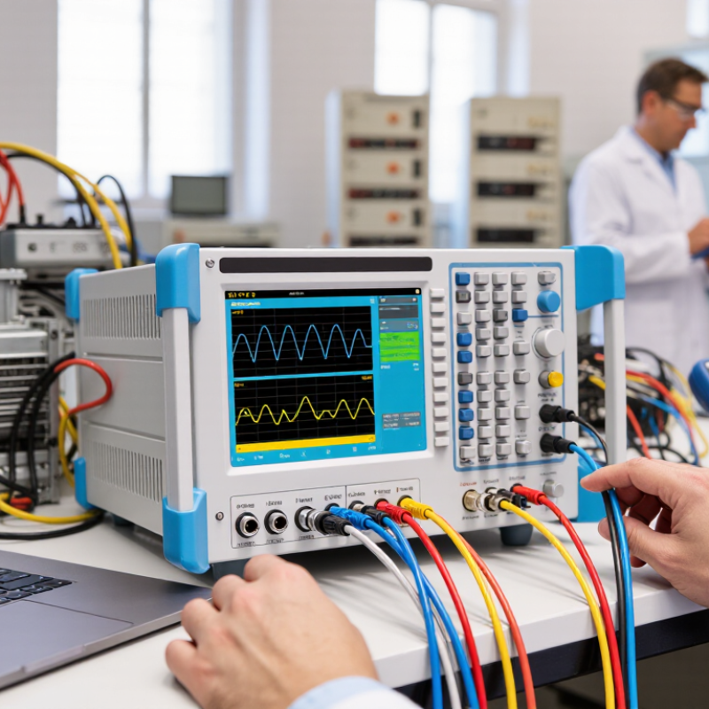
How to Choose Precision Digital Power Analyzers?

Define the Measurement Requirements and Application Conditions

Choosing a precision digital power analyzer starts with defining the measurement requirements, not browsing a product catalog. Record voltage, current, frequency, power factor, and expected waveform distortion. Include normal and worst-case values. A 230 V input may produce sharp switching spikes. These spikes can exceed the displayed RMS value. Measure peak voltage and peak current separately. Decide whether you need single-phase, three-phase, or DC channels. Specify accuracy for real power, not only voltage and current. A small phase error can distort low-power readings. This detail is often missed.

Application conditions shape the instrument choice. For inverter testing, check bandwidth, sampling speed, crest-factor capability, and channel synchronization. For standby measurements, confirm low-current resolution and stable readings near zero. Motor tests may require rapid changes, regenerative power, and bidirectional measurement. In production, response time and repeatability may matter more than maximum bandwidth. In a laboratory, traceable calibration and documented uncertainty are essential. I also inspect cable length, sensor placement, and grounding before trusting a result. A perfect specification cannot repair poor wiring.

Temperature, humidity, vibration, and available space deserve written limits. Confirm input isolation and the safe operating category for the installation. Check whether external sensors introduce phase shift or extra uncertainty. Record the setup with photographs and connection notes. Repeat the measurement. Results should remain similar. If they do not, inspect the fixture before changing the analyzer. I have seen clean waveforms hide loose terminals and incorrect sensor orientation. That experience changed my checklist. Leave room for uncertainty. Requirements sometimes change after the first test.

Compare Accuracy, Resolution, Bandwidth, and Sampling Performance

Choosing a precision digital power analyzer starts with the measurement question, not the display size. Accuracy tells you how close the reading is to reality. For low-power standby tests, a 0.1% error can hide meaningful energy losses. The U.S. Department of Energy’s 2022 standby-power guidance commonly uses a 0.5 W threshold, so resolution below 1 mW may be valuable in sensitive tests. Resolution is not accuracy. I once trusted a five-digit display that repeated the wrong result.

Bandwidth determines whether the instrument captures switching edges and harmonic content. IEC 61000-4-7 recommends measurement methods for harmonics up to 9 kHz, while IEEE 1459-2010 defines power quantities under distorted waveforms. A narrow bandwidth may smooth real waveform distortion. Excessive bandwidth, however, can increase noise. Sampling performance matters just as much. The sampling rate should exceed twice the highest frequency of interest, according to the Nyquist principle. In practice, engineers usually leave substantial headroom for transient shape and anti-alias filtering. A 1 MS/s system may be adequate for slow inverter studies, but inadequate for fast switching events.

Tips: Match accuracy to the smallest expected reading. Check bandwidth at the stated amplitude, not only at maximum input. Ask whether sampling is simultaneous across channels. Verify phase accuracy, especially when power factor approaches zero. Review uncertainty data from calibration reports, not advertising claims. IEC 61000-4-30 Class A methods can guide power-quality comparisons, but they do not replace application-specific validation. Build a test with a known resistive load, a distorted load, and a repeatability check. Small oversights remain common.

Evaluate Measurement Functions, Channels, and Power Ranges

How to Choose Precision Digital Power Analyzers?

Selecting a precision digital power analyzer starts with measurement functions, not screen size. True-RMS voltage and current are essential for distorted waveforms. Add active, reactive, and apparent power measurements for complete energy analysis. Power factor and phase angle reveal inefficient loads. Harmonic analysis and total harmonic distortion help identify switching losses and wiring problems. The International Energy Agency’s Electricity 2024 report estimates that data centers used about 460 TWh globally in 2022. That demand may exceed 1,000 TWh by 2026. Small measurement errors can become expensive at this scale.

Channel design matters just as much. A single-channel instrument may suit a basic load test, but three-phase converters require simultaneous voltage and current measurements. Four-wire capability is valuable when neutral currents or unbalanced loads matter. Check whether channels share a sampling clock. Otherwise, phase and power calculations may drift. Isolation ratings deserve close attention. The U.S. Department of Energy’s Motor Systems Market Assessment reports that motor-driven equipment represents roughly 68% of industrial electricity use in the United States. Motor tests therefore need inrush capture, waveform recording, and reliable low-power readings.

Power range selection is less obvious. A large maximum range can reduce resolution during standby measurements. A narrow range may clip startup surges. Look for multiple ranges, crest-factor specifications, bandwidth, and sensor compatibility. Wider is not always better. I have seen apparently accurate readings fail because the current probe was poorly matched. That detail is easy to miss. Compare uncertainty across the full operating range, not only at the rated load. Industry reports provide context, but your actual waveform decides the analyzer’s value.

Assess Connectivity, Software, Calibration, and Data Management

Choosing a precision digital power analyzer requires more than checking voltage and current accuracy. Connectivity, software, calibration, and data management determine whether measurements remain useful after testing. The IEA’s Electricity 2024 report projects global electricity demand to grow by an average of 3.4% annually through 2026. That pressure makes traceable efficiency data increasingly valuable. Choose interfaces that support stable Ethernet, USB, or fieldbus communication. Confirm whether the instrument can export raw data, timestamps, harmonics, and uncertainty values.

Software should display trends clearly, not bury them under decorative charts. Look for automated test sequences, role-based access, audit trails, and open file formats. These features support repeatability across laboratories and production sites. ISO/IEC 17025 emphasizes competent testing and traceable calibration. Ask for calibration intervals, uncertainty statements, and environmental limits. A certificate alone is not enough. I have seen teams archive reports but lose the measurement settings that made them meaningful. That is a data-management failure, not a minor inconvenience.

Tips: Test the analyzer with your real workflow before purchasing. Send one dataset to your database and review every field. Check whether files remain readable after software updates. Use synchronized clocks across instruments. Keep raw data, processed results, calibration records, and operator notes together. A perfect dashboard is not the goal. Reliable evidence is. Review storage permissions carefully, because convenient access can weaken control. Lastly, document exceptions honestly; imperfect records are easier to improve than hidden gaps.

Select the Analyzer by Balancing Performance, Compatibility, and Cost

Choosing a precision digital power analyzer begins with the measurement, not the product brochure. Start with the waveform. Define voltage, current, frequency, power factor, and expected transients. A motor drive may produce sharp harmonics, while a standby supply demands stable readings at very low power. Select enough bandwidth and sampling speed to capture those details without adding noise. Accuracy matters, but stability matters too. Look for stated uncertainty across temperature, range, and crest factor. A single headline accuracy figure can hide important limits.

Compatibility protects your investment. Check input ranges, sensor interfaces, isolation requirements, and available connection methods. The analyzer should fit your test bench, control software, and safety procedures. Confirm whether it supports harmonic analysis, standby measurements, efficiency calculations, and synchronized channels. Ask for calibration records with traceability. That evidence is more useful than a polished sales claim. In practical testing, I also check setup time. A device that takes ten minutes to configure can slow every engineering review.

Cost should include accessories, calibration, training, software, and future service. The cheapest option can become expensive. I once focused too heavily on purchase price and overlooked unsuitable current sensors. The first measurements looked reasonable, but the sensor range weakened low-load accuracy. That mistake changed my selection process. Compare complete measurement workflows, not isolated specifications. Request sample data, test the analyzer with a known load, and review repeatability between operators. Leave room for uncertainty. Real laboratories are rarely as clean as the specification sheet.

How to Choose Precision Digital Power Analyzers? - Select the Analyzer by Balancing Performance, Compatibility, and Cost

Analyzer Class Typical Measurement Accuracy Bandwidth Sampling Capability Typical Input Configuration Power and Voltage Coverage Best-Fit Applications Compatibility Considerations Indicative Equipment Cost
Basic Bench Analyzer Approximately ±0.1% to ±0.2% of reading, plus range-dependent error DC to approximately 100 kHz Approximately 100 kS/s to 1 MS/s per measurement channel 1 to 3 voltage or current channels; direct input for low-energy circuits Low-voltage DC and single-phase AC measurements; typically suitable for power levels below 1 kW Power supply checks, battery testing, adapter evaluation, and laboratory troubleshooting Confirm input connectors, shunt requirements, isolated channels, and the voltage category before connection About US$1,000–US$4,000
General-Purpose Precision Analyzer Approximately ±0.05% to ±0.1% of reading, depending on range, power factor, and calibration conditions DC to approximately 500 kHz Approximately 1 to 2 MS/s per channel; waveform capture for switching events 2 to 4 voltage/current channels; isolated inputs are commonly available Single-phase and selected three-phase measurements; commonly used from low-voltage electronics to several kilowatts AC/DC converters, inverters, motor drives, lighting equipment, and efficiency testing Check whether the analyzer supports the required wiring mode, current sensor type, crest factor, and communication interface About US$4,000–US$10,000
High-Accuracy Power Analyzer Approximately ±0.01% to ±0.05% of reading for specified operating ranges DC to approximately 1 MHz Approximately 1 to 5 MS/s per channel with synchronized voltage and current acquisition 3 to 6 isolated channels; supports external current shunts, probes, or transducers Single-phase and three-phase systems; suitable for precision efficiency, standby-power, and harmonic measurements Energy-efficiency certification work, inverter characterization, motor testing, and design validation Verify sensor phase shift, bandwidth limits, integration time, power-factor performance, and required calibration traceability About US$10,000–US$25,000
Wide-Bandwidth Dynamic Analyzer Approximately ±0.02% to ±0.1% of reading, with accuracy affected by frequency and sensor selection DC to approximately 2 MHz or higher Approximately 5 to 20 MS/s per channel; designed for transient and switching analysis 2 to 6 synchronized channels; high-bandwidth voltage inputs and compatible current probes High-speed switching converters, wide-bandgap semiconductor systems, and high-frequency motor-drive research Confirm probe bandwidth, propagation delay, common-mode rating, insulation category, and synchronization between channels About US$15,000–US$40,000
Multi-Channel Production and Research System Approximately ±0.02% to ±0.1% of reading, based on installed modules and test configuration DC to approximately 100 kHz–1 MHz, depending on the selected input module Approximately 1 to 10 MS/s per channel with continuous logging and synchronized acquisition 6 to 16 or more voltage/current channels; modular or rack-mounted architecture Multiple converters, multi-phase systems, traction platforms, battery packs, and automated test stations End-of-line testing, powertrain development, parallel device comparison, and long-duration energy studies Evaluate software APIs, SCPI or Ethernet control, data formats, trigger routing, channel isolation, and automation support About US$25,000–US$80,000+

Values are typical selection ranges for instrument classes rather than guaranteed specifications. Final performance depends on the measurement range, current sensor, bandwidth setting, crest factor, temperature, wiring method, and calibration conditions.

FAQS

What should I define before choosing a precision digital power analyzer?

Record voltage, current, frequency, power factor, and expected waveform distortion. Include normal and worst-case values. Measure peak values separately. A 230 V input may produce sharp switching spikes. Also define single-phase, three-phase, or DC requirements. Specify real-power accuracy, not voltage accuracy alone.

Why are accuracy and resolution different?

Resolution shows small display changes. Accuracy shows closeness to the true value. A five-digit display can still repeat the wrong result. For sensitive standby tests, resolution below 1 mW may help. Match accuracy to the smallest expected reading. This detail is often missed.

How much bandwidth and sampling speed are necessary?

Bandwidth must capture switching edges and relevant harmonics. A narrow setting may smooth real distortion. Excessive bandwidth can increase noise. Sampling should exceed twice the highest frequency of interest. Leave extra margin for transient shape and filtering. A 1 MS/s system may miss fast switching events.

What measurement functions are useful?

True-RMS voltage and current support distorted waveforms. Active, reactive, and apparent power provide broader energy information. Power factor and phase angle expose inefficient loads. Harmonic analysis can reveal switching losses and wiring problems. Keep the useful functions.

How many channels are needed?

A single channel may suit a simple load test. Three-phase converters usually need simultaneous voltage and current measurements. Four-wire capability helps with neutral currents and unbalanced loads. Confirm that channels share one sampling clock. Otherwise, phase calculations may drift.

How should I choose the power range?

A large range may reduce standby resolution. A narrow range may clip startup surges. Look for multiple ranges and crest-factor capability. Check sensor compatibility too. Wider is not always better. Compare uncertainty across the full operating range.

What should I check during inverter or motor testing?

Check bandwidth, sampling speed, channel synchronization, and transient capture. Motor tests may need inrush recording and bidirectional power measurement. Regenerative operation can reverse the power direction. Low-power readings should remain stable. I would not trust only a smooth display.

Which application conditions can affect measurement quality?

Record temperature, humidity, vibration, available space, grounding, and cable length. Confirm input isolation and safe installation limits. External sensors may add phase shift. Loose terminals can hide behind clean waveforms. Photograph the setup and repeat the measurement.

How can I validate an analyzer before regular testing?

Use a known resistive load, a distorted load, and a repeatability check. Review calibration uncertainty, not only advertised accuracy. Repeat the same connection several times. If results change, inspect the fixture first. My checklist still changes after unexpected tests.

Conclusion

Choosing the right Precision Digital Power Analyzers begins with clearly defining the measurement requirements and application conditions. Consider the voltage, current, power levels, waveform types, operating environment, and whether the analyzer will be used for laboratory testing, product development, production verification, or system monitoring. Accuracy, resolution, bandwidth, and sampling performance should then be compared to ensure the instrument can capture both steady-state values and fast-changing electrical events reliably.

It is also important to evaluate measurement functions, channel count, input configurations, and available power ranges. Connectivity options, control software, calibration support, and data management features can significantly affect testing efficiency and long-term usability. The best selection balances measurement performance with compatibility, ease of integration, operational flexibility, and total cost. By considering both current needs and possible future applications, users can choose an analyzer that delivers dependable results without paying for unnecessary capabilities.

Amelia

Amelia

Amelia is a highly skilled marketing professional with a strong understanding of the company’s products, customers, and industry landscape. With a thoughtful, research-driven approach, she transforms complex product information into clear, practical, and engaging content that helps readers make......