
Selecting the right Bench-top Frequency Converters requires more than comparing output power and price. A laboratory converter may look compact, yet its internal design determines measurement stability, motor behavior, and equipment safety. The wrong choice can create audible noise, unstable loads, or inaccurate test results.
Dr. Ned Mohan, a respected power-electronics educator, has emphasized, “A power converter must be selected as part of a system, not as an isolated component.” This principle guides the seven practical tips in this article. Each tip examines a decision that engineers often underestimate, including input compatibility, frequency range, waveform quality, voltage regulation, load capacity, cooling, and protection features. Small details matter. A converter operating beside sensitive instruments should not introduce excessive electromagnetic interference. A unit driving an induction motor may need stronger overload handling than its nameplate suggests.
Real benches are rarely perfect. Cables become longer. Loads change. Ventilation gets blocked. Specifications can also be misunderstood. That is why experienced users inspect efficiency curves, transient response, connector quality, and service support before ordering. Numbers alone are not enough.
Look beyond the front panel.
This guide does not promise one universal solution. Laboratory work varies, and even a carefully chosen converter may need additional filtering or monitoring. However, a structured evaluation reduces expensive mistakes and improves repeatability. The goal is simple: match the Bench-top Frequency Converters to the actual experiment, not to an attractive brochure.
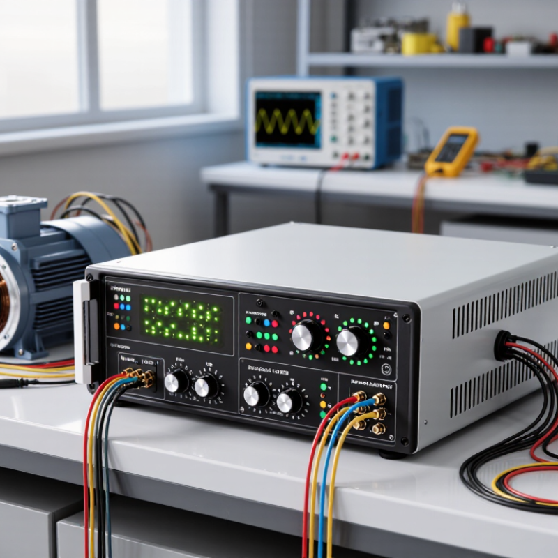
Before choosing a benchtop frequency converter, define the equipment’s frequency, voltage, and phase requirements. Check the nameplate, service manual, and test procedure. A 50 Hz motor may not perform correctly at 60 Hz, even when the voltage appears suitable. Small differences matter.
IEC 60038 lists standardized supply voltages, but laboratories often operate with regional variations. Record the input voltage as a range, not one number. For example, specify 230 V ±10%, 50 Hz, single-phase. Then confirm the converter’s continuous rating, starting capacity, and output regulation. A converter rated only for steady-state current may fail during motor acceleration. I have seen selections based on wattage alone. That is an easy mistake.
Phase requirements deserve equal attention. Identify whether the load needs single-phase input, three-phase output, or phase conversion in both directions. Some instruments also require a clean neutral reference. IEEE 519-2022 uses 5% voltage total harmonic distortion as a commonly applied limit for systems rated up to 1 kV at the point of common coupling. A converter should therefore be assessed for waveform quality, not frequency alone. Ask for measured THD data under your actual load. Published laboratory results are useful, but they may not match your cables or load profile. Test it.
When choosing a benchtop frequency converter, match its capacity to the connected equipment, not merely the test label. Check continuous power and short-term demand. A small motor may draw several times its running current during startup. Resistive heaters behave differently. They usually need steady power, while pumps and compressors create brief surges.
Read the equipment nameplate, then confirm actual current with a suitable meter. Nameplate figures can be optimistic. Surges matter.
Convert the load into apparent power, measured in volt-amperes, and compare it with the converter’s continuous VA rating.
Leave practical headroom, often 20 to 30 percent, for startup, temperature, and future accessories. Do not rely only on watts. Power factor can raise input current, especially with motors or electronic supplies.
A converter rated for 1,000 VA may struggle with a 700-watt inductive load. That mismatch is easy to miss. Allow extra room.
Check overload duration, output waveform, cooling, and duty cycle before connecting sensitive instruments. A unit near its limit may become hot, noisy, or unstable after an hour. Keep ventilation openings clear and reduce the load in warm rooms.
In testing, I would run the real equipment through several cycles, not switch it on once. My earlier mistake was sizing from normal running current alone. It passed the first test but failed under repeated starts.
Record voltage, current, and case temperature during that trial.
When choosing a benchtop frequency converter, inspect waveform quality before comparing convenience features. A stable frequency cannot compensate for distorted voltage.
Connect an oscilloscope directly at the output terminals. Check the sine wave at no load and under rated load. Look for flattened peaks, ringing, and sudden asymmetry. Measure total harmonic distortion with a suitable analyzer when possible. A clean display is useful, but it can still hide high-frequency noise. Probe grounding can also create false distortion.
Output stability deserves equal attention. Monitor voltage and frequency during startup, warm-up, and load changes. A reliable converter should recover quickly after a motor, transformer, or electronic load begins operating. Record regulation across several minutes, not just one reading. Temperature matters. Components may drift after an hour, especially in a crowded laboratory. Allow proper warm-up time before judging performance.
Read the technical specifications carefully. Confirm whether accuracy applies to the full load range or only ideal conditions. Ask for data on crest factor, transient response, protection behavior, and measurement uncertainty. In practical testing, I would compare the converter against a calibrated reference and repeat the test on different days. One measurement is not evidence. I have also seen apparently stable units produce uneven waveforms with nonlinear loads. That detail is easy to miss, and it can affect sensitive instruments. Consider leaving extra capacity instead of operating continuously at the limit. Oversizing is not always efficient, but it may improve stability.
A benchtop frequency converter can look simple until a motor behaves differently under changing loads. Compare control features using the equipment you actually run. Check whether the unit offers clear speed adjustment, stable frequency settings, and an accessible display. A large readout helps when you are standing beside a noisy test bench. Useful controls should also make it easy to set acceleration and deceleration times. Otherwise, a motor may start abruptly or take longer to settle than expected. Small details matter.
Safety functions deserve the same close attention. Look for overload protection, temperature monitoring, and a clearly marked emergency stop where appropriate. Check how the converter responds to a fault: does it show a readable code, or merely stop? A predictable response can save time during troubleshooting. Still, built-in protection is not a substitute for correct wiring, suitable ventilation, or the equipment manual. I have seen overlooked airflow turn a routine test into an unnecessary shutdown. That part is easy to miss.
Connectivity shapes how well the converter fits into a test setup. Inspect the available interfaces and confirm they work with your control system, data logger, or computer. Ask whether operating values and fault history can be read remotely. A connection that only supports basic commands may not provide enough detail for repeatable testing. Also check cable access and software requirements before purchase. It is tempting to assume “compatible” means effortless. It may not. Test the communication path with your intended setup, including the actual cable length and nearby electrical noise.
A benchtop frequency converter should fit the test, not merely fit the workbench. Check input and output ratings, waveform quality, frequency range, and overload capacity. Leave practical headroom above the maximum load. A converter operating near its limit often runs hotter and ages faster. This is where judgment gets messy.
Size affects cooling. A compact enclosure saves space, but restricted airflow can raise internal temperature quickly. Check the manufacturer’s derating curve at your real ambient temperature. DOE motor-system guidance reports that motor-driven systems consume about 62% of electricity in U.S. manufacturing, making conversion losses worth measuring carefully (U.S. DOE, Improving Motor and Drive System Performance, 2014). Use a thermal probe during a typical test cycle. Do not trust room temperature alone.
Maintenance should be visible and realistic. Look for accessible filters, replaceable fans, clear fault logs, and simple calibration procedures. A converter that needs specialist service for every small fault may cost more than expected. Calculate total cost across five years: purchase, electricity, inspection, spare parts, downtime, and training. The European Commission’s energy-efficiency assessments repeatedly emphasize lifecycle cost over purchase price. I would also compare standby consumption, which is easy to overlook. Seven minutes of daily checking can prevent an expensive failure. Yet, even careful estimates remain imperfect; load patterns change, and laboratory use is rarely consistent.
| Tip | What to Assess | Practical Checks | Why It Matters |
|---|---|---|---|
| 1. Match the electrical requirements | Confirm input voltage and frequency, output voltage and frequency, phase configuration, and the equipment’s rated power and current. | Read the load nameplate and compare its requirements with the converter’s continuous output ratings. Check whether the load needs single-phase or three-phase power, and whether it has a high starting current. | A converter that does not match the load may fail to start it, trip under load, or provide unsuitable power. Allow for the load’s actual operating and startup requirements rather than relying on a power rating alone. |
| 2. Check the footprint and installation space | Consider the unit’s dimensions, weight, benchtop area, cable access, and the clearance required around air inlets and outlets. | Measure the available workspace and check the installation guidance for ventilation clearances. Include room for connectors, controls, and safe access during operation. | A compact enclosure can save space, but an undersized or poorly ventilated location can restrict cooling and make routine operation or servicing harder. |
| 3. Evaluate the cooling method | Identify whether the converter uses forced-air cooling, natural convection, or another specified cooling arrangement. | Check the rated ambient-temperature range, ventilation requirements, and whether fan noise or airflow could affect the workspace. Keep dust and obstructions away from vents. | Heat affects component life and can cause thermal protection to reduce output or shut the unit down. Cooling needs depend on the design, load, and operating environment. |
| 4. Review controls and output quality | Assess the frequency and voltage adjustment range, display readability, control resolution, output regulation, and waveform specifications. | Compare documented specifications with the test equipment or device being powered. Check for relevant protections, such as overload, overtemperature, and short-circuit protection. | Suitable controls and documented output characteristics help ensure repeatable tests and reduce the risk of applying power outside the load’s allowable limits. |
| 5. Consider maintenance and serviceability | Find out which parts require periodic inspection or cleaning, whether filters are fitted, and how accessible the enclosure and service points are. | Review the operating and maintenance manual for cleaning instructions, inspection intervals, fan or filter replacement guidance, and service arrangements. Do not open energized equipment. | Accessible maintenance can reduce downtime. Following the manufacturer’s instructions helps preserve airflow and supports safe, reliable operation. |
| 6. Check compatibility and safety | Verify connector types, grounding requirements, operating environment, applicable safety documentation, and any required installation or use restrictions. | Confirm that cables and connectors are rated for the expected voltage and current. Check that the output suits the connected equipment and that protective earth and other safety provisions are appropriate. | Electrical compatibility and safe setup are essential. A converter is not automatically suitable for every load simply because its voltage and frequency settings appear to match. |
| 7. Compare total cost of ownership | Look beyond purchase price to include energy use, accessories, installation, maintenance, service, and expected downtime. | Compare quoted specifications and warranty terms. Estimate operating cost using the unit’s input power under the expected load, local electricity rates, and planned hours of use. | A lower initial price may not represent the lowest lifetime cost if the unit consumes more energy, needs additional accessories, or is harder to maintain. |
Note: Verify ratings, clearances, operating limits, and maintenance requirements in the specific converter’s documentation before purchase or use. Actual performance depends on the model, load, and installation conditions.
Check the equipment’s voltage, frequency, and phase requirements. Read the nameplate and service manual. Record voltage as a range, such as 230 V ±10%, 50 Hz, single-phase.
A motor designed for 50 Hz may perform poorly at 60 Hz. Small frequency differences can change speed, heating, and operating behavior. Voltage alone is not enough.
Check continuous output, starting capacity, and regulation. Motor acceleration can demand more current than steady operation. Selecting by wattage alone is an easy mistake.
Use an oscilloscope at the output terminals. Inspect the sine wave without load and under rated load. Look for flattened peaks, ringing, and asymmetry.
Monitor voltage and frequency during startup, warm-up, and load changes. Record readings for several minutes. Components may drift after an hour of operation.
Not always. High-frequency noise may remain hidden. Probe grounding can also create false distortion. Use a suitable analyzer when possible, and verify the measurement method.
Look for overload protection, temperature monitoring, and a clearly marked emergency stop when appropriate. Check whether faults produce readable codes or only stop the unit.
Test the converter with your actual equipment. Check speed adjustment, frequency settings, display readability, and acceleration controls. Abrupt starts can delay testing or stress motors.
Confirm compatibility with your control system, computer, or data logger. Test the actual cable length and nearby electrical noise. “Compatible” may not mean effortless.
Extra capacity may improve stability during demanding loads. Oversizing can reduce efficiency, though. The better choice depends on measured load behavior, not guesswork alone.
Choosing the right Bench-top Frequency Converters starts with understanding the power needs of your application. Confirm the required input and output frequencies, voltage levels, and phase configuration, then check that the converter can support the connected equipment’s rated power and any startup demand. A suitable capacity helps prevent overloads and supports reliable operation. Also consider waveform quality and output stability, especially when testing or powering equipment that is sensitive to variations in frequency or voltage.
Compare practical features such as adjustable controls, clear displays, safety protections, and connectivity with your test setup. The unit’s size, cooling requirements, and maintenance needs also matter, particularly when workspace is limited or the converter will be used frequently. Finally, weigh the purchase price against operating costs, upkeep, and expected service life. Considering these factors together can help you select a converter that fits your technical requirements and your working environment.